For any one needing to verify or find i2c address of
device or module and constantly needing to reprogram a controller just for the
exercise could be a big nuisance and time wasting. Using a very
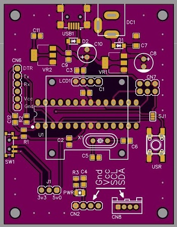
inexpensive ATmega168 chip we build a simple PCB with hand full of small
parts we build a custom PCB that can be fitted to a custom 3d printed box.
The board can be powered via DC barrow jack which is routed to 5v regulator to
prevent burning the processor and anything that is connected to it. There is a
secondary optional 3v3 regulator that is switched via J1 or SW1 which in turns
powers the tested device. NOTE, make sure only one is used.
A 2.54 and 2.0 mm connectrs are used for connecting to the test targets and
0.96" oLED display is used to display discovered devices/modules. Optionally
results are also send to the serial port used in the FTDI connector. To prevent
any overlap with address of the display, scanning bus is isolated and the i2c
protocol is simulated in software as the ATmega168 or the 328 only have single
hardware i2c bus.
The provided sample code will fit onto ATmega168, however due to popularity the
ATmega328 is less expensive to purchase and it can be programmed as Arduino UNO
The boards are available for purchase on our
Tindie store.
Features
ATmegega168 or ATmega328
controller based
0.96" oLED display for visual display
serial (via FTDI) for terminal display
2.54 and 2.0mm connectors
user button solder jumper selects reset or D2 line to expand
software
mini B
or DC barrow
power input
5 and 3.3 volt regulators
for target devices, switch or jumper selectable
Schematic (display & controller
board)
PCB laybout on EasyEDA
3D main case (stl)
Sample code