| |
- Porting our
original
indicator project to Atmel family controller and changing some of the
fundemental operation of how the inputs are done. Also as we wanted a
multi-color display the borrowed LED matrix from other project uses bi-color LED
chips turning the display in essence to 3 colors or a pattern of
combination of the 2 colors by enabling or disabling particular pixel color.
More on that in the software function.
The original design relied on too many connections between the controller and
display it self, 12 for the display and 9 for selector for 6 speed manual
transmission. The count would be less for say 5 speed or automatic
transmissions.
In this design, display had been separated onto its own pcb board which contains
some logic chips to drive the LEDs and a processor board containing naturally
the processor, voltage regulator and sensors/switches connections. Additionally
inputs are triggered by grounding it rather then connecting to the matrix logic
making it safer triggers and possibly avoiding damaging the processor or display
or both by incorrect wiring.
To help in the design, hall effect sensors that are used for detecting which
gear the transmission is in have open collector so they can safely be wired
directly into the processor with some safety in mind.
To help with wiring and packaging of it all, it was decided to split the project
into 2 parts not counting the hall effect sensors as location of them would be
different for each and different shifter design. So a connector for sensor
harness is provided for each sensor and simply the hall sensor board is either
soldered directly to the wires or plugged via connector or a combination of.
As the processor board would require most of the wiring it was decided that it
would be located somewhere with in the tunnel under the shifter boot and a thin
cable be running from it to the shifter knob where drive circuitry be located
for the display and display board it self. Not closed of to option the display
could be located outside of the shift knob it self if one preffers.
Processor board
Build around ATmega4808, the board was build specifically for this purpose,
though it may serve other purposes possibly in the future projects. The processor
is ideal for this purpose as it has build in clock to run at very fast frequency
and large number of I/O pins all packaged in a very small surface mounted chip
requiring very little external passive components making the circuit
simplified and compact. With 14 possible inputs for gear selections or other
digital inputs SPI connector to the display and
additional serial and I2C ports provided through additional second connector for
expansions or possibly driving different sub boards like OLED displays.
To
power the board from 12V car power system, onboard 5v regulator
produces stable supply to the processor and accompanying circuitry.
For any one wishing to expand connection of the board into cars communication
systems it can be interfaced via Single Wire low speed CAN or faster high speed
CAN transceivers. However as they are fired to same CAN UART, only one of the
transceivers can be used at a time.
Display
The LED matrix uses 35 0606 led chips however they are 4 pin with 2
leds per package making 70 in total. To make it more interesting is that the
colors are wired independantly so in essence has two independent 5x7 matrices of
2 colors. But the neet thing is that they can be rotated 180 degrees and primary
colors would change.
To drive the 35 or 70 LEDS a row colum drivers are required for which there are
just as many drivers options. Using a set of shift registers for simple
interface and 16 bits. With 12 bits (7 rows 5 columns) required for each
matrix provides a bit of an issue to drive 2 of those matrixes. However adding 2
buffers as parallel to the first shift register and wiring enable pin to second
register different bit allows for enabling each color with once single column
scan
For a very compact packaging of the 2 boards and to eliminate any possible
connectors the shift register board had been designed in a way to contain all
the components on one side and have interconnecting solder pads on other side.
This provides a way to solder the display board to the decoder board making a
single dual sided board
The 74hc595 registers on the control board alone are responsible for decoding of
which pixel is activated in the matrix. The as the data is being shifted out its
selecting row on one register and column on second register with last 2 most
significant bits controlling which color is selected by means of activating
buffers on the 74hc244 driver.
Assembly of the display board was designed to fit into our custom shift knobs.
We will be producing boards with mounting holes in the future and on request.
Software
The decoded or shift register board is designed around 2 shift registers and 2
buffers enabling respective colors. So basically whats needed is a scanner of
rows and colums. One register controls which row is active and the other
register controls which dots in the row to turn on and which color to enable.
A sample pattern for letter 'N' is below. With MSB on left controlling the
color buffers and bit 6 & 7 high turn on both buffers thus mixing colors
resulting in purple from red & blue combination
This is a pattern of N
B01x10001,
// Row 1: * *
B01x11001,
// Row 2: ** *
B01x10101,
// Row 3: * * *
B01x10011,
// Row 4: * **
B01x10001,
// Row 5: * *
B01x10001,
// Row 6: * * x
B01x10001
// Row 7: * *
The provided sample code writen for manual transmission and as it would be hard
to sense neutral position, we are defaulting N when nothing is sensed. This way
we will have N when in neutral and in between switching gears. When any other
gear is selected respective pattern will be selected and sent to the display.
The program can be very easily adapted to automatic transmission just by
switching character pattern.
The code however is not suitable for sequential transmissions like you find it
in motorbikes. as you would need to keep track which gear the bike is in and
change based on shift.
Features
3 color mixing
lower wire count
interconnection between processor and display
safer trigger inputs by utilizing hall effect sensors
processor board features Single wire GMLAN 33.3Kb or flex CAN
drivers
fast ATmega4808 processor
Schematics
LED
Shift register board
Processor board
PCB layout
Shift register board Gerber files
Processor board Gerber files
hall effect board
Bill of Materials
Sample program ATmega328P no CAN
implementation
Processor board 3d STL files
Shifter knob sample
Display board cavity requirement example
|
| |
|
|
|
|
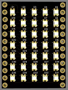
LED display (non casolated)
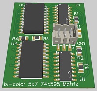
Shift register
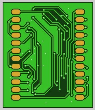
Shift register (back)
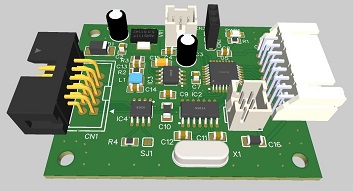
processor board

HALL effect sensor PCB
|